International Journal of Environmental Pollution and Remediation (IJEPR)
ISSN: 1929-2732

Volume 3 - Year 2015 - Pages 16-26
DOI: 10.11159/ijepr.2015.003
Guidelines for Preliminary Design of Funnel-and-Gate Reactive Barriers
Benoît Courcelles, Ph.D.
Polytechnique Montréal, Department of Civil, Geological and Mining Engineering
CP 6079, Succ. Centre-Ville, Montréal, Qc, H3C 3A7, Canada
benoit.courcelles@polymtl.ca
Abstract - Permeable Reactive Barriers represent an innovative remediation technique of contaminated aquifers. Three geometric configurations are encountered in the literature: a continuous wall, a funnel-and-gate system, and a caisson configuration. The present paper is focused on the design of the second and third geometric configurations and presents an analytical solution of the flow in a Permeable Reactive Barrier based on the Schwarz-Christoffel transformation. This analytical solution is coupled to residence time calculations to define a methodology of design taking into account the most important parameters on the design of a PRB: cut-off width, slenderness of the reactive cell, and hydraulic conductivity. Finally, the study provides a guidance diagram for the design of funnel-and-gate or caisson configurations, as well as a case study.
Keywords: Permeable Reactive Barrier; Contamination; Groundwater; Analytical study; Design.
© Copyright 2015 Authors - This is an Open Access article published under the Creative Commons Attribution License terms. Unrestricted use, distribution, and reproduction in any medium are permitted, provided the original work is properly cited.
Date Received: 2014-09-26
Date Accepted: 2015-01-20
Date Published: 2015-02-05
Nomenclature:
- α1, α2, α3, α4: External angles in the Schwarz-Christoffel transformation
- γ: Complex number in the Schwarz-Christoffel transformation
- Φ: Velocity potential
 : Difference of velocity potential between two wells in an infinite domain [m]
 : Difference of velocity potential between two points in a uniform velocity field [m]
- ψ: Stream function
- D: Thickness of the aquifer [m]
- f: Schwarz-Christoffel transformation
- g: Inverse of the Schwarz-Christoffel transformation
- hu-hd: Hydraulic head loss in a filter [m]
- kfilter: Hydraulic conductivity of a filter [m/s]
- Lfilter: Length of a filter [m]
- q: Flow rate per meter of depth of aquifer [m2/s]
- Q: Total flow rate in a filtering gate [m3/s]
- R: Half-length of the cut-off wall [m]
- Rd: Radius of a drainage element [m]
- Sfilter: Cross-surface of a filter [m2]
- T: Residence time [s]
- V0: Initial velocity [m/s]
- χA, χB, χC, χD: Real constants in the Schwarz-Christoffel transformation
- χS: Abscissa of the stagnation point (z-diagram) [m]
- yp: Half-width of the capture zone entering a well (z-diagram) [m]
- Yp: Half-width of the capture zone entering a PRB (z'-diagram) [m]
- Ys: Ordinate of the stagnation point (z'-diagram) [m]
1. Introduction
Permeable reactive barriers (PRBs) constitute a passive remediation technique for the treatment of polluted groundwater [1]. Their principle relies on the exploitation of hydraulic gradients to treat the groundwater in a reactive media able to degrade, adsorb or precipitate the pollutants.
Three main geometric configurations are available in the literature: (a) a continuous wall (CW) composed of reactive trenches or injection wells [1]; (b) a funnel-and-gate configuration (F&G) composed of two impermeable walls that direct the contaminated plume towards a filtering gate [2]; and (c) a caisson configuration (CC) similar to the previous one, but in which the flow in the filtering gate is in the upward direction [3].
As regards the implementation of each configuration, continuous walls represent the common type of PRB [1]. A design methodology is dedicated to this configuration and relies on the residence time of pollutants in the reactive media [4, 5]. On the contrary, only few practical tools are available in the literature for the design of funnel-and-gate PRBs and they are particularly focused on the hydraulic behaviour of PRBs [6-8]. However, the design of such PRBs relies on three technical aspects: (a) the reactive media must be appropriate to the pollutants, (b) the filters' size must be large enough to ensure a sufficient residence time [9-11], and (c) the reactive material must have a sufficient hydraulic conductivity to prevent any bypass of the system. The first aspect is a key issue in the design of PRBs and a particular attention has to be dedicated to the selection of the reactive or sorbent material when installing any PRB system [12]. The present paper will consider that the reactive media is selected adequately and the compatibility with the contaminant is not an issue.
Another key aspect for the design of the technology is an adequate site characterization [13]. Hydrologic characteristics of groundwater flows represent a challenge for the design of PRBs [14]. Assuming that the reactive material is adequately selected from laboratory tests, the two interdependent parameters for the design of PRBs are the residence time and the hydraulic capture width. Residence time refers to the contact time between the contaminated groundwater and the reactive media within the barrier. It ensures that the reactive barrier is large enough to meet regulatory requirements. Hydraulic capture width refers to the maximal width of the contaminated groundwater that can enter a filtering gate or go through a continuous wall.
Numerical modeling constitutes the most popular option for the design of PRBs and commercial software products such as MODFLOW [15] and FLONET [16] are extensively used to evaluate the effect of PRBs on regional flows. Nevertheless, this approach is cost and time consuming. Moreover, the comparison of alternative methods or geometries needs the preparation of different numerical models, as performed by Hudak [17]. To face this problem, several authors have considered an analytic approach for preliminary design and optimization of PRBs. Thus, Craig and al. chose the Analytic Element Method (AEM) to represent a continuous wall in a homogenous aquifer [18]. Their model was based on an elliptical inhomogeneity placed in a uniform flow as a representation of a PRB. This approach constituted a first step in analytical modeling and provided useful tools for preliminary designs. To expand on the approximation of an elliptic geometry, Klammler and Hatfield investigated another approach based on conformal mapping and obtained solutions for flow fields around a rectangular continuous wall [19]. This approach has been later extended to funnel-and-gate and drain-and-gate configurations [6,7] and the authors analysed the solutions for flow fields regarding widths and shapes of the capture zones under different scenarios. These anterior works are particularly useful for preliminary design of F&G, but they are mainly focused on hydraulic aspects of the design. As the residence time in reactive filters is an essential element, the originality of the present paper consists in considering the residence time as an additional criterion for preliminary design of permeable reactive barriers.
2. Schwarz-Christoffel theorem
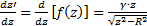
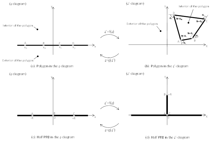
The Schwarz-Christoffel theorem states that the interior of a closed polygon may be mapped into the upper half of a plane [20]. This transformation is illustrated in Fig. 1.a and b, where the function f transforms the real axis in the z-diagram into a polygon in the z'-diagram. The inverse transformation is represented by the function g. Eq. 1 represents the Schwarz-Christoffel transformation.

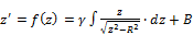
where γ is a complex number in the z-diagram; f is a complex function; xA, xB, xC, xD, ... are real constants in ascending order of magnitude; α1, α2, α3, α4, ... are external angles of the polygon. Considering α1=/π2; α2=-π and α3=π/2, Eq. 1 becomes Eq. 2 and transforms the real axis (Fig. 1.c) into a polygon with two apexes at infinity (Fig. 1.d). In particular, this transformation states that a flow around a cut-off wall perpendicular to a uniform flow can be deduced from a uniform flow without any PRB. Indeed, the x-axis can be considered as a no-flow boundary condition for a uniform flow parallel to this axis in the z-diagram (Fig. 1.c). In the z'-diagram (Fig. 1.d), this no-flow boundary is transformed into the negative part of the x'-axis, two segments [AB] and [BC] along the y'-axis, and the positive part of the x'-axis. Considering [AB] and [BC] as the upstream and downstream sides of an half cut-off wall, the basic set of boundary conditions in the z-diagram is mapped over a more complex geometry in the z'-diagram. As the flow in the lower half of the z'-diagram (respectively z-diagram) can be deduced from the flow in the upper half by symmetry, the analytical solution will be established for Y>0 (respectively y>0).
where R is a real positive number equal to the half-length of the cut-off wall. After integration (Eq. 3) and introduction of two set of images, f (z=0) = iR and f (z=R) = 0, the analytical expressions of the function f and its inverse function g are respectively given in Eq. 4 and Eq. 5.
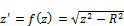

Introducing the real and imaginary part of complex numbers z = x+iy and z' = X+iY, Eq. 5 can be rewritten as:
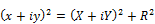
Development and separation of the real and imaginary parts leads to the following system of equations where the origins in the z and z'-diagrams are not considered in the domain (apex of the polygon in the z'-diagram):
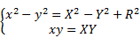
This system of equations is easily solved and leads to a fourth order polynomial whose roots are given in Eq. 8. Considering that y is strictly positive in the upper half of the z-diagram, the expression of y is given in Eq. 9.
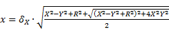
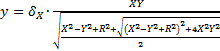
where δX represent the sign of X. The previous equations are particularly interesting because they represent a flow around a cut-off wall. In the next section, the geometry will be complicated by permitting a flow across the cut-off wall at the origin. This additional boundary condition represents the filtering gate (reactor)
2.1. Complex potential Ω around a PRB
In the present model, the widths of the cut-off wall and the reactive zone are neglected in comparison to the dimensions of the regional groundwater flow. Moreover, the filtering gate is represented by a sink and a source located respectively upstream and downstream of the cut-off wall. This assumption is particularly interesting to represent the flow in the z'-diagram as a function of a simple geometry in the z-diagram. Indeed, if we consider a sink located at point A and another at point C in the z-diagram (see Fig. 1.c), the image in the z'-diagram becomes a funnel-and-gate PRB.
Considering a steady, uniform and irrotational flow in the z-diagram, Eq. 10 represents the velocity potential ϕ and the stream function Ψ.

where V0 is a constant velocity parallel to the x-axis in the z-diagram. Considering a sink and a source of equal strength q respectively located at (-R,0) and (+R,0) in an initially static aquifer, the velocity potential and the stream function ϕ are given in Eq. 11 [21].
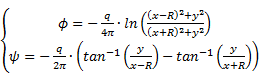
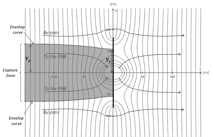
where q is the flow rate per meter of depth of the aquifer (m2/s). According to the superposition principle, the addition of Eq. 10 and Eq. 11 gives the velocity potential and the stream function of a uniform flow influenced by a sink and a source. Replacing x and y by Eq. 8 and 9, we obtain the velocity potential and stream function around a PRB. This potential function has been introduced into Winplot-2d and the equipotential lines are illustrated on Fig. 2 for a cut-off wall of 160 m coupled with a sink and a source of 12 m2/d. This figure also illustrates the capture zone and the by-pass of the PRB (groundwater laterally away from the x'-axis, outside of the envelope curve).
As regards the hydraulic design of a PRB, the
width of the plume caught by the filtering gate constitutes the most important
information to be known. To determine this width, we studied the envelope curve
in the z-diagram and considered its transformation by the function f.
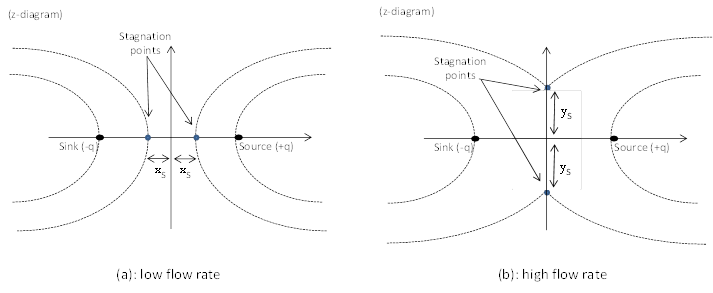
Looking at the stagnation points in the z-diagram, three configurations can be
observed depending on the magnitude of the flow rate q. These
configurations are: (a) two stagnation points on the x-axis (Fig. 3a), (b) a
stagnation point at the origin, or (c) two stagnation points on the y-axis
(Fig. 3b). In the last case, some flow occurs from the source to the sink
(recirculation). Considering that the sink and the source are connected through
the filtering gate, this configuration cannot be encountered on the field and
the water always goes from the sink to the source via the reactor. In the
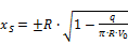
z-diagram, the abscissas of the two stagnation points (xS in
Fig. 3.a.) are given in Eq.12 and we can easily demonstrate that their images
are located on the y'-axis of the z'-diagram. Their ordinates YS
is given in Eq. 13. As Ys cannot be higher than R
(half-length of the cut-off wall), the maximum flow rate q that can
enter the filtering gate is  .
.

Moreover, the formulation of the stream line towards the stagnation point in the z-diagram is given in Eq. 14 [21].
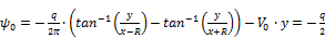
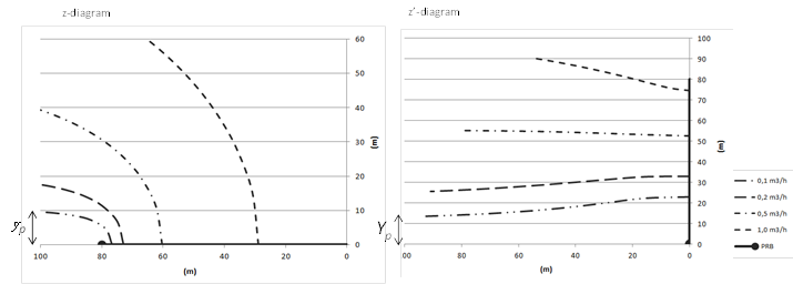
Considering the limit of
the stream function when  (
( ), we obtain the half-width of the capture zone
entering the reactor (see Eq. 15 and Yp in Fig. 4.b.).
), we obtain the half-width of the capture zone
entering the reactor (see Eq. 15 and Yp in Fig. 4.b.).

Combining Eq.14 and 15, we can demonstrate that the half width of the capture zone is proportional to q and inversely proportional to the initial velocity of the flow V0 (see Eq. 16).

To illustrate the displacement of the envelope curve as a function of the flow rate q, different values of q from 0.1 to 1 m2/h are introduced in Eq. 14 and the solutions are provided on Fig. 4. For every single x∈├]-∞;χS], the corresponding ordinate y is calculated thanks to the Generalized Reduced Gradient method (GRG) due to the non-linearity of Eq. 14. The image of the envelope curve has then been calculated in the z'-diagram. The capture width Yp is smaller than the ordinate Ys of the stagnation point for small flow rates, whereas Yp is greater than Ys for high flow rates. Nevertheless, this illustration cannot yet be considered as a real flow net around a PRB as the flow rate in the reactor q is not a boundary condition, but is imposed by the geometry of the reactor and its related hydraulic head losses. As a consequence, the model is extended in the next section by considering the geometry of the reactor and its impact on the flow rate.
2.2. Flow rate in a filtering gate
The previous
representation of the filtering gate means that the velocity potentials are
respectively set to - and + at the sink and the source. This assumption
represents a bias because the velocity potential must be a continuous function
across the reactor and the values at the entrance and the exit must be finite.
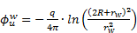
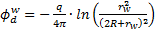
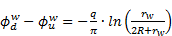
To be more realistic, we considered the radius rw of two
wells representing the sink and the source in the z-diagram. Thus, the velocity
potentials upstream (
and + at the sink and the source. This assumption
represents a bias because the velocity potential must be a continuous function
across the reactor and the values at the entrance and the exit must be finite.
To be more realistic, we considered the radius rw of two
wells representing the sink and the source in the z-diagram. Thus, the velocity
potentials upstream ( ) and downstream (
 ) related to these two wells are defined in Eq. 17
and 18 and their difference is given in Eq. 19.
) related to these two wells are defined in Eq. 17
and 18 and their difference is given in Eq. 19.
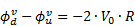
This difference is
combined to  (velocity potential induced by a uniform velocity
field in the z-diagram) to obtain the overall velocity field presented in Eq.
21.
(velocity potential induced by a uniform velocity
field in the z-diagram) to obtain the overall velocity field presented in Eq.
21.

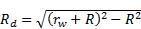
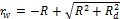
As rw represents the radius of the gravel pack around the wells in the z-diagram, we can easily demonstrate that the image of the gravel pack around the sink (respectively the source) is a half-gravel pack located upstream (respectively downstream) of the cut-off wall in the z'-diagram. The radius of gravel packs in the z'-diagram (Rd) can be deduced from the function g (see Eq. 22).
Otherwise, Darcy's law in a reactive filter states that the flow rate Q entering a filtering gate is proportional to its hydraulic conductivity, its surface and the hydraulic gradient. Considering that the head losses are generated by the porous media and negligible for all pipes or draining trenches that can be implemented at the entrance and the exit of the PRB, the flow rate in the reactive filter is provided in eq. 24.
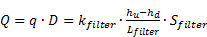
where kfilter [m/s] represents the hydraulic conductivity of the filter, Sfilter [m2] and Lfilter [m] respectively represent its cross-surface and length, hu-hd [m] represent the hydraulic head loss between the entrance and the exit of the filter, Q is the flow rate in the filtering gate [m3/s], q is the flow rate per meter of depth of the aquifer [m2/s], and D is the thickness of the aquifer [m].
Considering that  in the z-diagram, the combination of Eq. 21, 23
and Eq. 24 leads to the flow rate in a PRB (Eq. 25).
in the z-diagram, the combination of Eq. 21, 23
and Eq. 24 leads to the flow rate in a PRB (Eq. 25).
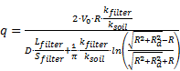
This equation represents the flow rate per meter of aquifer that can enter a filtering gate. For design purpose, the geometry of the filter (Sfilter and Lfilter), its hydraulic conductivity (kfilter), the radius of the drainage elements (Rd) and the width of cut-off walls (R) have to be selected according to the site conditions: q (minimum flow rate to be treated with respect to the width of the plume), V0 (Darcy velocity of the groundwater on the site) and ksoil (permeability of the aquifer).
2.3 Residence time as a function of the flow rate
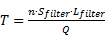
The first part of this paper was dedicated to the hydraulic aspect, which does not constitute the sole parameter for the design of a PRB. Indeed, the void volume of a filtering gate must be large enough to ensure a sufficient residence time. As a consequence, the design of a PRB must involve hydraulic and chemical considerations to prevent (a) any by-pass of the system, and (b) the break-through of the filter. The residence time T in a filter is deduced from the total flow rate Q and the porosity n of the reactive media, as mentioned in Eq. 26.
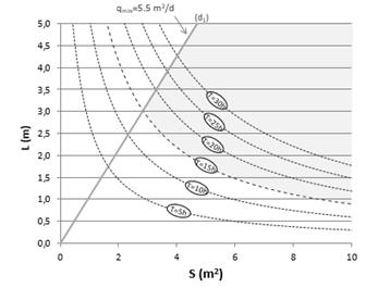
Isovalues of residence time can thus be plotted in the (Sfilter, Lfilter) plane, as presented on Fig. 5 for the following parameters: V0=40m/yr, R=80 m, n=0.4, Rd= 1.25 m, and kfilter/ksoil =10. All couples of surface and length above a hyperbola generate a residence time greater than the corresponding isovalue and satisfy the chemical criterion. Fig. 5. Also contains a straight line corresponding to a specified flow rate qs according to Eq. 25. All points under this line represent a higher flow rate than the specification (qs). According to this figure, two conditions have to be satisfied simultaneously for the selection of a filter: (a) the residence time must be higher than the target, that is to say that the coordinates (Sfilter, Lfilter) must be above a selected hyperbola, and (b) the flow rate must be higher than qs, that is to say that the coordinates (Sfilter, Lfilter) must be under the straight line. Combining the two previous conditions, a region of optimal geometry can be plotted as illustrated in grey on Fig. 5.
3. Practical application
Fig. 5 is a useful tool for the design of a PRB but it has to be redrawn when modifying the boundary conditions. To prevent this redrawing and to facilitate the design made by practitioners, Eq. 25 and 26 have been rewritten in terms of dimensionless variables.
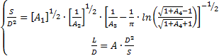
where the dimensionless parameters are:

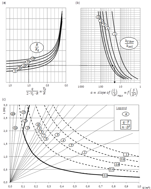
The system of Eq. 27 has been implemented in a guidance diagram provided on Fig. 6. This figure aims to design a PRB for all sets of boundary conditions and has to be used as follow:
- Considering the width
of the plume Yp, select a cut-off wall length that meets

- On Fig. 6.a, plot a vertical line at the corresponding A3 = Yp/R and mark the intersection with the curve corresponding to the radius of the draining element (A4 = Rd/R),
- Plot an horizontal line from this point and mark the intersection with the curve corresponding to the ratio A2 = kfilter/ksoil (See Fig. 6.b),
- Plot a vertical line from this point and note the value of α corresponding to the intersection with the abscissa. α represents the slope of the upper boundary of the optimal geometry region in the (Sfilter, Lfilter) plan (see Fig. 6.c).
- Calculate the ratio A1 = q.T/n.D2 and select the corresponding hyperbola on Fig. 6.c. This hyperbola constitutes the lowest boundary of the optimal geometry region in the (Sfilter, Lfilter) plan.
- Select a filter section and length in the optimal region.
Considering the shape of the curves on Fig. 6.a., the design diagram demonstrates that a cut-off wall longer than 10 Yp (i.e. Yp /R > 0.2) significantly increases the hydraulic efficiency of the system. With this assumption, a ratio kfilter/ksoil higher than 10 prevents any hydraulic issue. Indeed, the optimal region becomes mainly influenced by the residence time (slope of the upper boundary higher than 100).
In summary, the guidance diagram is useful for designers to choose the primary dimensions of a new PRB. Nevertheless, any designer has to keep in mind that the approach proposed here relies on the following implicit assumption: the width of the permeable reactive zone is extremely small relative to the total width. Hence, the reactive zone is essentially treated as a point feature and the head distribution in the vicinity of a more realistically dimensioned PRB would vary noticeably from heads generated from the model proposed here. Moreover, the initial hydraulic gradient is supposed uniform throughout the model, which can vary from the reality. As a consequence of these hypothesis, the model should be used for primary design only and to prevent a lot of trials and errors in the modelling.
4. Case study
For illustration purposes, a case study has been performed on a specific site characterized by the following elements:
- a width of plume Yp equal to 10 m,
- an aquifer with a thickness of 3 m, and an hydraulic conductivity of 3.10-5 m/s,
- a gradient of 0.004, which leads to a flow rate to be treated of 113.5 m3/y (40 m3/y per meter of depth).
The contamination is composed of heavy metals (copper and zinc) and the treatment is based on the precipitation of metal hydroxides performed through an increase of pH. The targeted pH depends on the valence of the metals: a pH of about 10 allows the precipitation of hydroxides from divalent metal ions (Zn, Mn, Cu, Pb, Ni, Co and Cd), while a pH of around 6-7 is adapted to trivalent ions (Fe, Al, Cr). In our case, magnesium oxide has been selected as the pH at the equilibrium with pure magnesium oxide is around 10, which is particularly interesting for the precipitation of bivalent ions. Laboratory tests leaded to a minimum residence time of 120 h and the reactive media is characterized by a permeability of 18.10-5 m/s and a porosity of 0.3.
These
characteristics lead to dimensionless parameters A1 and A2
respectively equal to 0.2 and 6. To evaluate the parameters A3
and A4, a length of 20 m has been chosen for the cut-off wall (2R).
A higher value could be considered, but cut-off walls are expensive and
practitioners try to minimize their length. A lower value could also be
considered, but the safety factor decreases as R approaches  . Considering a typical draining trench with a
radius of 1 m, the construction on the guidance diagram leads to an optimal
region above the black bold lines on Fig.6.c. (α = 20 and A1 = 0.2).
. Considering a typical draining trench with a
radius of 1 m, the construction on the guidance diagram leads to an optimal
region above the black bold lines on Fig.6.c. (α = 20 and A1 = 0.2).
The final dimension of the filter is then determined by practical consideration. For instance, shortest filters will be preferred to facilitate their manipulation. Limiting the length of the filter to 1 m, the minimum surface to warranty a sufficient residence time would be of 0.2 m2, hence a radius of 0.5 m.
5. Conclusion
Based on the Schwarz-Christoffel transformation, we developed an analytical solution of the flow rate in a PRB. This study demonstrated that the cut-off width has the most important impact on the capture zone and it leads to a design methodology for the reactive cell. According to this methodology, the section and length of a reactive cell are selected to ensure (a) a minimum flow rate, and (b) a minimum residence time in the porous media. The first condition is essential to capture the entire plume, while the second is mandatory to treat efficiently the contaminated groundwater. To meet these conditions, the design of a funnel-and-gate PRB comprises two steps: (a) a minimum cut-off width is selected to ensure a sufficient capture width, and (b) the filter's dimensions are selected on figure taking into account hydraulic and chemical constraints (residence time).
References
[1] D. W. Blowes, C. J. Ptacek, et al., "Passive Remediation of Groundwater Using in Situ Treatment Curtains," Geoenvironment 2000: Characterization, Containment, Remediation, and Performance in Environmental Geotechnics, vol. 1-2, no. 46, pp. 1588-1607, 1995.
[2] D. C. McMurtry and R. O. Elton, "New Approach to in-Situ Treatment of Contaminated Groundwaters," Environmental Progress, vol. 4, no. 3, pp. 168-170, 1985. View Article
[3] S. D. Warner, C. L. Yamane, et al., "Considerations for Monitoring Permeable Ground-water Treatment Walls," J. of Environmental Eng., vol 124, no, 6, pp. 524-529, 1998. View Article
[4] R. M. Powell, D. W. Blowes, et al., "Permeable Reactive Barrier Technologies for Contaminant Remediation," NASA, Washington, 1998. View Article
[5] A. R. Gavaskar, "Design and Construction Techniques for Permeable Reactive Barriers," J. of Hazardous Materials, vol. 68, no. 1-2, pp. 41-71, 1999. View Article
[6] H. Klammler and K. Hatfield, "Analytical Solutions for the Flow Fields Near Funnel-and-Gate Reactive Barriers with Hydraulic Losses," Water Resources Research, vol. 45, no. 2, Feb. 2009. View Article
[7] H. Klammler, K. Hatfield, et al., "Analytical Solutions for Flow Fields near Drain-and-Gate Reactive Barriers," Ground Water, vol. 48, no. 3, pp. 427-437, 2010. View Article
[8] H. Klammler, K. Hatfield, et al., "Capture Flows of Funnel-and-Gate Reactive Barriers Without Gravel Packs," Advances in Fluid Mechanics, vol. 69, pp. 319-330, 2010. View Article
[9] R. Rumer and J. Eds. Mitchell, "Permeable Reactive Barriers: Assessment of Barrier Containment Technologies: A Comprehensive Treatment for Environmental Remediation Application," Int. Containment Technol. Workshop, Baltimore, Maryland, 1995.
[10] K. D. Warren, R. G. Arnold, et al., "Kinetics and Mechanism of Reductive Dehalogenation of Carbon Tetrachloride Using Zero-Valence Metals," J. of Hazardous Materials, vol. 41, no, 2-3, pp. 217-227, 1995. View Article
[11] S. F. O'Hannesin and R. W. Gillham, "Long-Term Performance of an in Situ "Iron Wall" for Remediation of VOCs," Ground Water, vol. 36, no. 1, pp. 164-170, 1998. View Article
[12] I. Kozyatnyk, et al., "Evaluation of Barrier Materials for Removing Pollutants from Groundwater Rich in Natural Organic Matter," Water Sci. and Technol., vol. 70, no. 1, pp. 32-39, 2014. View Article
[13] F. Obiri-Nyarko, S.J. Grajales-Mesa, and G. Malina, "An Overview of Permeable Reactive Barriers for in Situ Sustainable Groundwater Remediation," Chemosphere, vol. 111, pp. 243-259, 2014. View Article
[14] S. Liu, X. Li, et al., "Hydraulics Analysis for Groundwater Flow Through Permeable Reactive Barriers," Environmental Modelling and Assessment, vol. 16, no. 6, pp. 591-598, 2011. View Article
[15] M. McDonald and A. Harbaugh, "A Modular Three-dimensional Finite-Difference Ground-Water Flow Model," in Techniques of Water-Resources Investigations Reports, book 6, ch. A1, US Geological Survey, 1988. View Book
[16] N. Guiger, J. Molson, et al., "Flonet v.1.02: Two-dimensional Steady-state Flownet Generator," Waterloo Centre for Groundwater Res., Univ. of Waterloo and Waterloo Hydrogeologic Software, Waterloo, Ontario, 1991.
[17] P.F. Hudak, "Comparison of Permeable Reactive Barrier, Funnel and Gate, Nonpumped Wells, and Low-Capacity Wells for Groundwater Remediation," J. of Environmental Sci. and Health, vol. 49, no. 10, pp. 1171-1175, 2014. View Article
[18] J. R. Craig, A. J. Rabideau, and R. Suribhatla, "Analytical Expressions for the Hydraulic Design of Continuous Permeable Reactive Barriers," Advances in Water Resources, vol. 29, no. 1, pp. 99-111, 2006. View Article
[19] H. Klammler and K. Hatfield, "Analytical Solutions for Flow Fields Near Continuous Wall Reactive Barriers," J. of Contaminant Hydrology, vol. 98, no. 1-2, pp. 1-14, 2008. View Article
[20] V. L. Streeter, "Handbook of Fluid Dynamics," New York, McGraw-Hill, 1948. View Book
[21] H. Chanson, "Applied Hydrodynamics: An Introduction to Ideal and Real Fluid Flows," CRC Press, 2009. View Book