International Journal of Environmental Pollution and Remediation (IJEPR)
ISSN: 1929-2732

Volume 13 - Year 2025 - Pages 75-83
DOI: 10.11159/ijepr.2025.009
Bidirectional Tidal Energy Conversion System
Balahuseyn Mirzayev
7, Cafar Cabbarly str., Nardaran, Baku, Azerbaijan
balahuseyn.mirzayev@gh.lukoil.com
Abstract - This paper introduces a novel tidal energy conversion concept specifically designed for low-range tidal environments (~1 m), where conventional tidal technologies are ineffective. The system employs a buoyancy–countermass coupled hydraulic design, capturing energy during both tidal uplift and gravitational descent. This bidirectional approach enables full utilization of tidal displacement, in contrast to turbine-based systems that harness only part of the flow. Key performance results indicate an overall efficiency of approximately 77%, straightforward modular scalability through caisson dimensioning and replication, and technical feasibility using existing offshore engineering practices. Together, these outcomes show that the system can be practically realized and adapted to different site conditions. By demonstrating that both feasibility and scalability are achievable, the study positions the proposed design as a practical foundation for new tidal energy solutions in underserved coastal regions. The concept represents a significant contribution to ocean energy research by showing that useful power can be generated even under minimal tidal ranges.
Keywords: Tidal energy conversion, countermass and buoyancy-couple, offshore power generation, new mechanical layout
© Copyright 2025 Authors - This is an Open Access article published under the Creative Commons Attribution License terms. Unrestricted use, distribution, and reproduction in any medium are permitted, provided the original work is properly cited.
Date Received: 2025-05-26
Date Revised: 2025-09-25
Date Accepted: 2025-10-08
Date Published: 2025-12-08
1. Introduction
Conventional tidal energy technologies, such as barrage systems or horizontal-axis turbines rely on large tidal head differentials or strong unidirectional currents, limiting deployment to a small number of optimal global locations. This research explores an alternative tidal energy conversion method suitable for open-sea sites with minimal tidal height variation. The system utilizes gravitational and buoyant forces to drive a bidirectional hydraulic generator in response to cyclic vertical sea-level changes.
Although some tidal energy concepts also operate bidirectionally, these typically employ turbines to exploit flood and ebb currents. In contrast, the proposed system is novel in that it leverages vertical tidal lift and descent, with both phases directly converted into hydraulic flow. Unlike turbine-based systems, which are limited by fluid dynamic conversion efficiency and cannot fully exploit tidal motion, the proposed buoyancy–counterweight hydraulic system converts the entire vertical tidal displacement into pressurized flow. The recoverable energy is therefore restricted only by the structural dimensions of the tidal lift caisson, offering greater potential scalability and a more direct utilization of tidal forces.
The novelty lies in the mechanical layout, which includes a vertically guided Countermass Gravity Block (CGB), lifted by a buoyant Tidal Lift Caisson (TLC), and coupled to dual piston-cylinder assemblies that pressurize a closed hydraulic circuit. Power is extracted via a hydraulic motor connected to a grid-synchronous generator. This paper presents the theoretical framework, design calculations, and component-level layout for a 1 kW pilot-scale system, including a full mechanical and hydraulic balance.
All components are selected or scaled for realistic deployment using existing marine and hydraulic technologies.
2. System layout and operation
The system consists of the following major components.
Seabed Anchoring Assembly:
- Fixed structural base that provides vertical guidance and load support
- Integrated guide rails prevent lateral displacement of the moving assembly
Tidal Uplift Cylinder Assembly (TUCA) / Gravity Descent Cylinder Assembly (GDCA):
- 2 oppositely oriented hydraulic cylinder-piston assemblies mounted atop the Seabed Anchoring Assembly
- Pistons are mechanically linked to the floating component — the Tidal Lift Caisson (TLC)
- The linkage configuration ensures that the TUCA and GDCA operate in opposite hydraulic cycles (suction/discharge) during each tidal stroke, upward or downward
- These cylinders are respectively engaged during the upward motion (tidal lift) and downward motion (gravity descent)
- Both assemblies drive hydraulic fluid into a high-pressure line for energy conversion
Tidal Lift Caisson (TLC):
- Link attached to the top cylinder-piston assemblies (TUCA/GDCA)
- Provides buoyancy lift during rising tide, - acts as vertical puller
Countermass Gravity Block (CGB):
- Reinforced concrete block acting as the primary gravitational energy source
- Located on the top of TLC
Hydraulic Lines:
- High-pressure lines run from both cylinders to accumulator bank and hydraulic motor input
- Return lines connected from motor back to piston reservoirs (closed loop)
Hydraulics and Generator:
- Required subsea enclosure and need to be subsea rated
- High-Pressure Buffer Accumulator (HPBA), - a 40-liter accumulator to maintain pressure continuity. The accumulator temporarily stores high-pressure fluid and releases it at a controlled rate to support continuous operation of the hydraulic drive motor.
- Hydraulic Circuit included flow control, return lines, and fluid reservoir
- Hydraulic Drive Motor (HDM), - a hydraulic motor for converting fluid pressure into shaft rotation. Standard hydraulic motors can maintain smooth output at low input flows [3].
- Grid-Sync Generator (GSG), - a standard 1500 RPM generator producing 50 Hz AC power
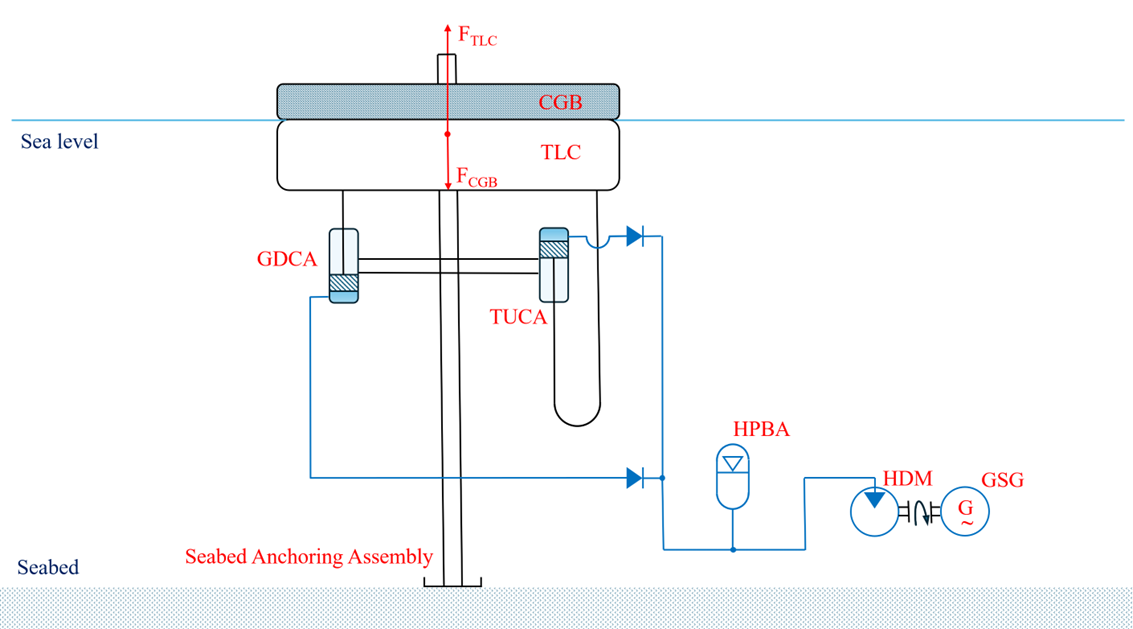
The upward stroke (TLC rise) engages TUCA, while the downward stroke (CGB fall) engages GDCA. Each piston stroke is designed to deliver sufficient pressure to maintain the generator shaft at required torque and speed, accounting for system losses. All forces, fluid volumes, and energy flows are calculated for a 6-hour tidal stroke.
3 Design Calculations
3.1 Energy & power
Net electrical output (design target) is 1.0 kW.
Let’s assume:
Mechanical transition efficiency as 95% - standard piston linkages exhibit 93–97% efficiency in well-lubricated, low-speed conditions [1],[2],[3];
Hydraulic motor efficiency as 85% - worst among all type of hydraulic motors referring to Target Hydraulics and Brendan Casey [4], [5];
Synchronous generator efficiency as 99% - for industrial machines [6], so let’s assume more realistic 95% for smaller scale machines.
Step-by-Step Efficiency Breakdown as per table below
Table 1: Efficiency Breakdown.
|
Stage |
Estimated Efficiency (%) |
|
Mechanical |
~95% |
|
Hydraulic (pumping, motor) |
~85% |
|
Generator (electrical output) |
~95% |
Total system efficiency:
ηtotal = 0.95 × 0.85 × 0.95 ≈ 0.77 or 77%
Total mechanical energy required for 1 kW continuous output over a 6-hour stroke is:
Pmech = 1.0/0.77 ≈ 1.3 kW = 1.3×10³ W
Time: T = 6 hrs = 21600 s
Energy per 6-hour tidal stroke:
E = Pmech × T = 1.3×103 ⋅ 21,600 = 28.08×10⁶ J = 28.08 MJ
3.2 Required force per 1m stroke
The force required to deliver 28.08 MJ of energy through the piston over 1-meter (h) vertical stroke is:
Fpiston = E/h = 28.08×10⁶/1 = 28.08×10⁶ N
Since the caisson must overcome both the force needed to generate hydraulic pressure (Fpiston) and the weight of the Countermass Gravity Block (𝐹CGB), which is designed to deliver a similar amount of energy during the descent phase, the total required lifting force becomes:
FTLC = Fpiston + FCGB = 28.08×10⁶ N + 28.08×10⁶ N = 56.16×10⁶ N
Here, the gravity block is dimensioned such that its gravitational force equals the force required to pressurize the hydraulic system: FCGB = Fpiston
3.3 Piston area at 350 bar (3.5×10⁷ Pa)
For feasibility calculations, the system pressure was set at 350 bar, which is within the standard continuous operating range of industrial and offshore hydraulic cylinders and motors [7], [8].
Then, the required area of the piston traveling over 1-meter stroke will be:
Spiston = Fpiston/P = 28.08×10⁶ N/3.5×10⁷ Pa = 0.8023 m2
Piston diameter:
Dpiston = 2 × √(0.8023/π) = 1.01 m
3.4 Hydraulics (flow rate and accumulator sizing)
Volume of the displaced fluid through any of cylinders (TUCA or GDCA) during single stroke:
V = Spiston × 1 m = 0.8023 m2
Flow rate:
Qflow = V/T = 0.8023/21600 = 3.71×10⁻⁵ m3/s
Assuming 5% of the transition gap to bridge flow during dead zones (Ttransition = 1080 s) the volume of accumulator needs to be:
Vacc = Qflow × Ttransition = 3.71×10-5 × 1080 = 0.04 m3 = 40 L
3.5 Caisson buoyant volume and dimensions
The caisson must generate 56.16×10⁶ N upward buoyant force during the upward stroke. The buoyant force acting on a submerged object equals the weight of the displaced water (Archimedes' Principle):
FTLC = ρwater × VTLC × g
Where,
ρwater - density of seawater, ~1025 kg/m³;
VTLC - submerged volume in m³ (assuming TLC is fully submerged) and
g - the standard acceleration of gravity, ~9.81 m/s2.
Let’s find the required volume of the caisson buoyant TLC:
VTLC = 56.16×10⁶/(1025 × 9.81) = 5585 m3
Let’s now estimate the dimensions of TLC assuming option with 50-meter height (HTLC) the cylindrical caisson:
V = πr2HTLC,
so, the diameter of the TLC:
DTLC = 2 × √ [5585/ (3.14 × 50)] = 11.9 m
Including the TLC’s own weight will increase the required draft by about 8% compared to the initial buoyancy-only calculation. So, allowing extra 8% (4m) to accounted for TLC self-weight, the final figures for caisson dimensions could be 54 × 12 meters cylinder.
3.6 Gravity block weight, volume and dimensions
The mass required to generate 28.08×10⁶ N of gravitational force, Fgrav = Fpiston:
mCGB = Fgrav/g = 28.08×10⁶/9.81 = 2,862,385 kg = 2,862.4 tons
If we use reinforced concrete ρRC=2,400 kg/m3, then:
VCGB = mCGB/ρRC = 2,862,385/2,400 = 1,192.66 m3
Let’s now estimate the dimensions of CGB assuming it is located on the top of TLC (occupying same area as TLC) to simplify the current design calculation. The height (HCBG) of the concrete layer is going to be:
HCBG = VCGB/ (π × DTLC2/4) = 1,192.66/(3.14 × 11.9 × 11.9/4) = 10.7 m
10.7 m thick reinforced concrete slab, 11.9 m diameter
4. Technology Readiness Assessment
Let’s evaluate each subsystem for feasibility using current (2025-level) industrial capabilities and with regards to baseline design parameters as per table below:
Table 2: Design Parameters.
|
Parameter |
Value |
|
Tidal range/Vertical stroke |
1 meter |
|
Continuous net electrical output |
1kW |
|
TLC dimensions |
11.9m diameter × 54m high |
|
CGB weight |
2,862 tons |
|
Hydraulic pressure |
350 bar |
|
Total mechanical energy per 6-hour tidal stroke |
56.16J |
Tidal Lift Caisson (TLC):
- Equivalent in scale to small floating dry docks, pontoons, or offshore caissons.
- Modular steel buoyancy tanks or reinforced concrete caissons of this size are commonplace
Feasibility: Fully buildable with current civil/marine engineering practices.
Countermass Gravity Block (CGB):
- Volume: ~1,193 m³ — e.g., 11.9 m dia × ~10.7 m thick cylinder.
- Similar in size to foundation segments for wind turbine monopiles or jacking platforms.
- Can be precast in modular segments and assembled on-site.
Feasibility: Well within construction norms.
TUCA/GDCA assemblies:
- Required force: 28.08 MN each
- Required pressure: 350 bar
- Piston area: 0.803 m² / Diameter ~1.01 m
These are very large hydraulic cylinders, but similar to:
- Offshore jacking cylinders
- Ship-lift pistons
- Civil lifting platforms
- Manufacturers like Bosch Rexroth, Parker Hannifin, and Enerpac offer solutions at this scale [9], [10].
Feasibility: Large, but standard for heavy offshore and infrastructure lifting
Hydraulic Drive Motor (HDM):
- Input: 350 bar, ~1.3 kW, Output: 1500 RPM mechanical drive shaft
- Maintaining smooth rotation from very slow, low-volume hydraulic input over 6 hours might be a challenge. This could be mitigated via application of hydraulic accumulator and flow control valves set to maintain constant motor speed
- Standard hydraulic motors (e.g. axial piston, bent axis) support these specs
Feasibility: Technically standard for precision hydraulic systems
Grid-Sync Generator (GSG):
- 1 kW @ 1500 RPM
- Industrial micro-generators widely available (diesel backup gensets, wind turbine alternators)
- Requires subsea-rated, oil-filled, pressure-compensated housing
Feasibility: Available
HPBA (Accumulator):
- Volume needed: ~40 liters at 350 bar
- Commercially available as Bladder-type (Parker, HYDAC) and Piston-type
- Rated for deep-sea oil & gas and hydraulic power units
Feasibility: Available
What Could Be a Challenge:
- Precise control of stroke phasing. Mitigation: use of flow sensors, valve banks, stroke limiters
- Achievable long-term sealing of large cylinders. Mitigation: use offshore-rated hydraulic seals, pressurized housings
- Structural mass transportation (CGB). Mitigation: precast in sections, tow-float to site, assemble at sea. Consider use of single semi submerged caisson partially filled with water both as TLC and CGB. Design considerations may follow existing offshore concrete structure codes such as DNVGL-ST-C502 [11].
- Long-term structural integrity of the large TLC unit (∅11.9 m × 54 m height). Mitigation: apply internal bracing and corrosion-resistant coatings; perform FEA validation under fatigue, heave, and pressure conditions; consider use of reinforced concrete over steel for cost and mass distribution control.
While the proposed tidal conversion system is technically feasible with existing industrial practices, 2 more practical risks must be acknowledged in the transition from concept to deployment:
- Maintenance at Sea: Offshore maintenance of hydraulic systems is logistically complex and costly. The system’s moving parts and submerged assemblies will require robust inspection and intervention strategies to ensure reliability over time.
- Mooring Stability: The buoyancy–countermass assembly is highly sensitive to vertical motion but must remain laterally stable. Mooring line fatigue, seabed anchoring reliability, and storm load resistance represent significant risks to long-term stability.
These factors do not undermine the fundamental feasibility of the concept but highlight the practical engineering hurdles that must be addressed during detailed design, prototyping, and pilot deployment phases. Recognizing these risks ensures that the concept is framed not only as technically sound but also as grounded in the operational realities of offshore energy systems.
5. Practicality and Economic Viability Assessment
With a tidal range of only one meter, the proposed buoyancy–countermass hydraulic system faces an inherent scale-to-yield challenge. Delivering approximately 1 kW of continuous output at ~77% assumed conversion efficiency requires ~28 MJ per half-cycle. This in turn demands piston forces of ~28 MN, and because the tidal lift caisson must also overcome the counterweight, the total upward buoyant lift reaches ~56 MN. Such forces translate into a caisson displacement of roughly 5,585 m³ and a gravity block of about 2,862 tons. Although technically feasible, this configuration is undeniably large for the modest power yield it delivers.
In terms of specific power, the result is on the order of 0.3 W per tonne of structure—significantly lower than small tidal turbines or wave devices, which achieve much higher values but rely on sustained current or wave regimes that 1 m tidal-range sites cannot provide. The strength of the concept therefore lies not in mass efficiency but in site access and predictability: it can harvest vertical displacement reliably in locations where horizontal flow systems would not function.
From a structural and operational perspective, a large SPAR-style caisson and multi-thousand-ton counterweight are feasible with offshore construction practices, but they raise challenges in fabrication, transport, mooring, and long-term inspection. Maintenance issues include seal wear under low-speed duty, corrosion of steel or creep in polymer alternatives, and biofouling. These challenges can be mitigated with modular fabrication, protective coatings, cartridge-style hydraulic seal packs, and designs that allow for remote inspection and replacement.
Economically, a single 1 kW unit is more of a technology demonstrator than a commercially viable product. Balance-of-system costs such as cables, switchgear, mooring, and deployment vessels do not scale down with unit size, leaving the cost per kW high. Practicality therefore depends on modular scaling: deploying multiple units in arrays that share infrastructure and operations. Such clustering can cut per-unit balance-of-system costs by 20–35% and improve O&M economics by enabling batch servicing.
In summary, while the one-meter version highlights the physical feasibility of the buoyancy–countermass approach, it also exposes the economic limitations of large infrastructure yielding modest power. The pathway to viability lies in efficiency refinements, mass-optimized structures, actuator simplification, and above all, array deployment. The concept should therefore be viewed not as a single standalone generator but as a scalable building block, whose real potential emerges when grouped into arrays and adapted to higher tidal ranges where energy yield per structure is inherently greater.
6. System Optimization Strategy
6.1 Mesotidal Optimization and Modular Array Deployment
In mesotidal environments with tidal amplitudes of about 3 m (representing ~13% of global tides [12]), the practicality of the buoyancy–countermass system improves significantly. Because usable energy per stroke scales directly with tidal range, moving from 1 m to 3 m allows the same 1 kW continuous output to be achieved with only one third of the buoyant force and counterweight mass. The tidal lift caisson volume falls from ~5,585 m³ to ~1,860 m³, while the gravity block mass reduces from ~2,862 tons to ~954 tons. This scaling eliminates the extreme mismatch between infrastructure size and yield that characterizes the 1 m case, resulting in a system that is easier to fabricate, transport, and install. A smaller SPAR-style caisson with reduced draft simplifies tow-out and mooring, while lighter reinforced or composite structures can further cut cost and corrosion risk. The specific power improves more than threefold, since the output remains the same but structural mass drops sharply.
Beyond mesotidal conditions, macrotidal sites with tidal ranges exceeding 3 m present even greater energy potential, as each additional meter of vertical excursion proportionally increases the extractable work per cycle. In such environments, the same system geometry could be operated at higher loads or reduced in size while still delivering substantial net power, offering a practical route to extend the concept toward medium-scale coastal generation without fundamental design changes.
The second pathway to improvement lies in scaling through arrays: modular groups of such compact units can share export cables, hubs, and other balance-of-system infrastructure, reducing per-unit cost by 20–35% and lowering installation and O&M overhead. By combining the natural advantage of mesotidal sites with the economy of scale offered by arrays, the system shifts from being a conceptual demonstrator toward a practical and economically competitive solution. This integrated approach shows that by targeting 3 m tide regions and deploying optimized arrays, the buoyancy–countermass design can achieve both technical feasibility and commercial relevance.
This favorable scaling trend establishes a practical foundation for quantifying how the system’s geometry, unit output, and array size evolve under higher tidal amplitudes, as examined in the following after next section Sizing Assessment section.
6.2 Layout and StEnSEA Integration (200 kW Net Output)
In order to improve the practicality of the Tidal Conversion (TC) concept, an optimization study was carried out based on integration with a subsea energy storage module (StEnSEA). The objective was to maintain a stable grid supply profile of 200 kW during off-peak hours and 300 kW during peak hours, using the bidirectional capability of TC units in combination with storage discharge.
The system configuration assumes multiple Tidal Conversion (TC) units coupled in parallel to drive two hydraulic motors: Motor 1 connected to the generator for continuous 200 kW grid supply, and Motor 2 dedicated to charging the StEnSEA module.
The calculation proceeds as follows:
6.2.1 Peak demand window (12 h, 07:00–19:00):
- Target supply = 300 kW
- TC continuous contribution = 200 kW
- StEnSEA contribution = 100 kW
- Required storage discharge energy:
Eout = 100 kW × 12h = 1.2 MWh
6.2.2 Accounting for storage efficiency (75% input and output losses in total):
- Charging energy required:
Ein = Eout / η = 1.2 / 0.75 = 1.6 MWh
6.2.3 Additional charging load during off-peak (12 h, 19:00–07:00):
- Extra charging energy above output = 1.6 – 1.2 = 0.4 MWh
- Average additional charging power:
Pch = 0.4 MWh/ 12h = 0.033 MW = 33 kW
6.2.4 Off-peak TC requirement:
- Grid delivery = 200 kW
- Plus charging = 33 kW
- Total = 233 kW
6.2.5 Energy balance:
- Two hydraulic motors:
- Motor 1 → Generator → Grid (direct supply)
- Motor 2 → StEnSEA pump mechanical drive
- Demand: 200 kW (off-peak), 300 kW (peak)
- StEnSEA efficiency: 75%
Table 3: Energy Balance at 75% Efficiency (12h off-peak /12h peak).
|
Period |
TC Output |
M1→Grid |
M2→StEnSEA |
Grid from StEnSEA |
Total Grid Supply |
|
Off-peak, 12h |
243kW |
200 kW |
43kW |
0 |
200 kW |
|
Peak,12h |
200 kW |
200 kW |
0 |
100 kW |
300 kW |
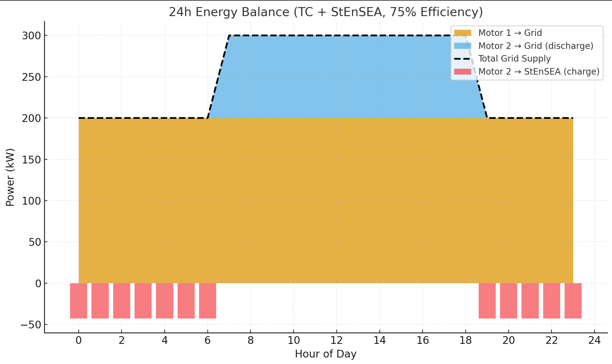
Interpretation:
Over the 12-hour off-peak period, the TCs must not only supply 200 kW directly to the grid, but also generate an additional 43 kW on average to recharge storage. This corresponds to an input of 1.6 MWh to achieve a usable 1.2 MWh discharge during the next peak window.
During the 12-hour peak period, the TCs sustain 200 kW continuous delivery, while the StEnSEA discharges at 100 kW, raising the total grid supply above the target 300 kW (refer to the Figure 2 below).
- Motor 1 always delivers 200 kW continuous to the grid.
- Motor 2 is the balancing channel:
- Off-peak: absorbs ~43 kW average to charge StEnSEA.
- Peak: reverses role, discharging ~100 kW to grid.
- The “extra” 43 kW is exactly the efficiency penalty (1.6 MWh in → 1.2 MWh out).
6.3 TC Sizing Assessment (3 m Tides, 200 kW Net Output)
6.3.1 Assumptions:
- Tidal stroke s = 3 m (semidiurnal regime, ≈4 strokes/day).
- Required continuous net electrical output Pnet=200 kW.
- Total system efficiency η ≈ 0.77 (mechanical × hydraulic × generator).
- Tidal Conversion (TC) unit design based on the previously established buoyancy–countermass equilibrium (FTLC = 2 × Fgrav), using the same practicable single-unit dimensions from the 1 m case (TLC diameter ≈12–16 m, CGB ≈2.8–4.0 kt).
6.3.2 Design Envelopes: Conservative, Balanced, and Practicable
For scaling studies, three envelopes were introduced to represent distinct levels of design ambition and associated engineering complexity. Conservative envelope – reflects a highly reliable, maintainable configuration where all mechanical components (seals, moorings, hydraulic linkages) remain comfortably within existing industrial limits. This configuration maximizes serviceability and minimizes structural stress but yields the lowest per-unit output. Balanced envelope – represents an optimized trade-off between constructability, efficiency, and compactness. It uses the same structural dimensions as the conservative case but assumes more efficient mechanical–hydraulic coupling and tighter control over parasitic losses. This envelope is considered the reference case for overall array sizing. Practicable (ambitious) envelope – reflects the upper boundary of what is still achievable using conventional offshore fabrication and lifting capacities. It assumes slightly higher structural loads, greater TLC draft, and optimized hydraulic ratios to achieve higher per-unit yield, while remaining physically buildable with known technologies.
Author’s Note: The term “Practicable” is used herein to define the upper boundary of engineering feasibility—a configuration that remains constructible and operable with existing offshore technologies, though at higher structural loads and fabrication effort. It is therefore labelled “Practicable (ambitious)” to distinguish it from purely theoretical or speculative cases. The Balanced envelope, by contrast, represents the optimum trade-off between technical ambition, cost, and maintainability, and is thus adopted as the reference scenario throughout the study.
6.3.3 Scaling Logic
With the TLC and CGB dimensions held constant, per-unit energy yield increases linearly with the tidal stroke h. Moving from 1 m to 3 m tides therefore triples the available mechanical work per stroke. Based on the 1 m reference results (1.0–1.5 kW per unit), each unit in 3 m tides would generate approximately 3.0–4.5 kW net electrical power.
Pnet, unit (3m) ≈ 3 × Pnet, unit (1m)
Table 4: Array Sizing for 200 kW Output
|
Design Envelope |
Estimated Net Power per TC Unit |
Units Required for 200 kW Output |
|
Conservative |
3.0 kW |
≈ 67 |
|
Balanced (reference) |
3.6 kW |
≈ 56 |
|
Practicable (ambitious) |
4.5 kW |
≈ 45 |
Interpretation
The results confirm that in 3 m tidal environments, a 200 kW output can be achieved by deploying between 45 and 67 TC units, depending on the selected design envelope. The balanced configuration (≈56 units) offers the most realistic compromise between manufacturing effort, operational stability, and energy yield.
This modular scaling approach ensures that individual TC units remain within the constructible range (TLC diameters ≤16 m, CGB ≤4 kt), avoiding the impractical mass and volume associated with oversizing a single device.
6.3.4 Scalability Potential
The scaling behaviour of the Tidal Conversion (TC) system is fundamentally linear: energy yield increases in direct proportion to both the tidal stroke height and the effective displacement (size) of the buoyancy–countermass pair. Consequently, sites with greater tidal ranges, or designs employing larger caisson diameters and counterweights, can achieve proportionally higher outputs per unit. Conversely, smaller geometries are still viable for micro-generation applications where power demand is modest but fabrication and deployment constraints dominate. This proportional scaling makes the TC architecture inherently modular—power capacity can be expanded by simply replicating units or modestly increasing caisson dimensions without altering the core mechanical principle.
6.4 Design, materials
A slender SPAR caisson (10–13 m diameter) with a small waterplane area can reduce wave loading, aided by keel heave plates and strakes to suppress vortex-induced vibrations. The splash zone should be tapered to minimize slamming, while a cellular shell with thin plating and ring/bulkhead supports improves strength-to-weight efficiency. Hybrid skins (FRP/HDPE over steel or RC) or precast RC rings with post-tensioning can lower costs and corrosion risks. Local reinforcement in the splash zone and wear bands at guide interfaces further enhance durability.
The tidal cylinders can be optimized by adopting large double-acting units that generate pressure during both lift and descent. Subsea-rated seals and low-friction wear rings improve efficiency and longevity, while adjacent accumulators and compact manifolds ensure smooth flow. Locating the cylinders in a dry moonpool or pressure-compensated housings enhances reliability and simplifies maintenance.
Structural improvements to focus on reducing weight while maintaining strength, using cellular framing with local reinforcement in the splash zone. Guided rails with replaceable wear pads to provide accurate vertical movement and allow easy servicing.
7. Conclusion
This paper presents a novel and modular tidal energy concept specifically designed for deployment in low-tide coastal environments where conventional tidal technologies are ineffective.
Compared to turbine-based tidal systems, which typically require tidal ranges of 4–7 m to operate economically (e.g. conventional barrage and current turbine designs [13], [14]), our buoyancy–countermass concept reduces the site threshold by ~75–80%, making tidal power viable even in ~1 m range environments
By focusing on scalable units with relatively small output (starting at ~1 kW), the design demonstrates strong potential for mass deployment in underserved or off-grid regions. Critical engineering challenges, such as stroke synchronization, mechanical-hydraulic efficiency, and structural stability, - are addressed through a technology readiness assessment. The system’s feasibility is further reinforced through the use of well-established technologies drawn from offshore oil and gas, floating platform design, and marine hydraulics.
References
[1] Brendan Casey. (2016, August 15). "How To Calculate Hydraulic Cylinder Efficiency" [Online]. Available: View Article
[2] D.Y. Voronov, V.V. Voloskov, A.O. Drachev, O.V. Boychenko, "Hydraulic Cylinders: Textbook and Methodological Manual", Togliatti State University (TSU), page 8, 2011
[3] M.V. Golub, "Characteristics of Power Cylinders: Methodical instructions", Brest State Technical University, page 6, 2012
[4] Target Hydraulics. (2025, September 19). "Specifications and Efficiency of Hydraulic Motors" [Online]. Available: View Article
[5] Brendan Casey. (2011, March). "Hydraulic Pumps and Motors: Considering Efficiency" [Online]. Available: View Article
[6] Lou van der Sluis. "Electrical Power Engineering, The synchronous machine" [Online]. Available: View Article
[7] Quiri Hydromécanique Group. "High-performance cylinders for all industrial applications" [Online]. Available: View Article
[8] Parker Hannifin Corporation. (2015) "Industrial Hydraulics" [Online]. Available: View Article
[9] Bosch Rexroth AG. (2021) "Hydraulic cylinders for offshore lifting and marine systems." Technical Brochure [Online]. Available: View Article
[10] Parker Hannifin Corp. (2022) "Compact Hydraulic Power Units and Piston Motors" [Online]. Available: View Article
[11] DNV, "Offshore Standards: Design of Floating Concrete Structures", DNVGL-ST-C502, 2018
[12] Joshua Stevens. (2024, October 21) "Taking Stock of Our Oceans' Tides" [Online]. Available: View Article
[13] Ocean Energy Council. "What is tidal energy?" [Online]. Available: View Article
[14] Solartech. (2025, September 5) "How Does Tidal Energy Work? The Complete Guide to Harnessing Ocean Power" [Online]. Available: View Article