International Journal of Environmental Pollution and Remediation (IJEPR)
ISSN: 1929-2732

Volume 5 - Year 2017 - Pages 15-19
DOI: 10.11159/ijepr.2017.002
A Study of Adaptive Cruise Control System to Improve Fuel Efficiency
Changwoo Park1, Hyeongcheol Lee2
1 Department of Electrical Engineering, Hanyang University
222 Whangsimni-ro, Seongdong-gu, Seoul, Republic of Korea, 133-791
Changwoo@hanyang.ac.kr
2 Department of Electrical and Biomedical Engineering, Hanyang University
222 Whangsimni-ro, Seongdong-gu, Seoul, Republic of Korea, 133-791
Hclee@hanyang.ac.kr
Abstract - This paper presents modelling and control strategy of adaptive cruise control system. The algorithm utilize the information of subject and target vehicles to against waste energy. The Control strategy operates to follow the preceding vehicle with the optimal fuel consumption speed trajectory while the target vehicle is in the control distance range. This algorithm focuses on reducing unnecessary acceleration and deceleration. The simulation is conducted by Matlab/Simulink® and CarSim® simulator to verify its effectiveness.
Keywords: Adaptive Cruise Control, Eco Drive, Fuel Efficiency, Energy Saving.
© Copyright 2017 Authors - This is an Open Access article published under the Creative Commons Attribution License terms. Unrestricted use, distribution, and reproduction in any medium are permitted, provided the original work is properly cited.
Date Received: 2015-09-14
Date Accepted: 2017-10-04
Date Published: 2017-12-20
1. Introduction
As globally increasing interest in environmental and energy issues, research in many field is being achieved a resolution of energy saving and environmental problems simultaneously improving fuel efficiency of automotive. Preceding studies have showed that high emission rates connected to the using fossil fuels and road traffic strongly affect the air quality in urban areas [1], [2]. In particular, for dealing with the problems, it is researched in its field to improve fuel economy of existing gasoline and diesel vehicles. There are important parts to develop a new material for reduction weight of chassis and to design vehicles shape for lower air resistance. [3], [4] Also industries try to find other systems for efficiency such as CVT (Continuously Variable Transmission) to be able to control engine speed on the optimal operation line. [5] In addition, hydrogen and electric vehicles have been developed and become wide spread as alternative conventional one with emissions of carbon dioxide (CO2) which causes greenhouse gas. [6], [7]
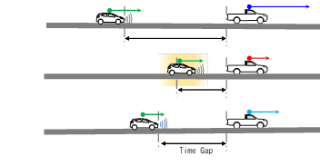
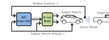
Despite these efforts, however, these studies are hard to apply in most vehicles because of high cost to develop new material or limit of structural problems. It is effective method improving fuel efficiency of vehicle not to only develop new system, but also controlling vehicle speed, acceleration and braking to against waste energy on the road. In this study, new vehicle speed control strategy is suggested based on the adaptive cruise control system. This system is automatically adjusting the subject vehicle speed to maintain safe distance from preceding vehicle.
An adaptive cruise control system is an extension of a cruise control system in conventional vehicles. [8] This system, generally, focus on following performance and keep the distance between subject and target vehicle while existing a vehicle ahead. The control algorithm in this paper suggests to change the reactivity depending on current circumstance of subject and target vehicle with flexible distance to maintain of safety.
2. Control Algorithm
The control algorithm in this paper is based on optimal control algorithm, linear quadratic regulation (LQR), so both errors and control input can be considered. One of errors is different of desired and actual relative distance and the other is relative velocity between subject and target vehicle. The control input is an acceleration of subject vehicle. This algorithm determines the optimal fuel efficiency acceleration as control input and guarantees safety.
While a vehicle accelerates rapidly, it causes more fuel consumption [9], [10]. It means that the vehicle should smoothly accelerate to improve fuel efficiency. If subject vehicle is controlled to follows target too slowly, however, it can give a room to collide when the target vehicle has emergency stop. To solve this problem, this control algorithm has variable acceleration weighting with two considered influences, relative distance and sign of target vehicle’s acceleration.
2.1. Active Linear Quadratic Regulation
Required acceleration is designed with LQR and the state equation can be written as follows:
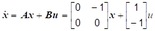

The ![]() is states matrix as error,
is states matrix as error, ![]() is control input as an acceleration of subject vehicle in Eqs. (1). The
is control input as an acceleration of subject vehicle in Eqs. (1). The ![]() is a desired distance
between target and subject vehicle and it is set by Time-gap.
is a desired distance
between target and subject vehicle and it is set by Time-gap. ![]() is an actual relative distance,
is an actual relative distance, ![]() and
and ![]() are each velocity of target and subject vehicle.
are each velocity of target and subject vehicle.
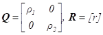
The goal of this optimal controller is to minimize a cost function of a state equation. The cost function contains error of relative distance and velocity as shown in Eqs. (3) below.
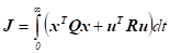
The weighting matrixes
![]() and
and ![]() are defined as below.
are defined as below.
In Eqs. (4), ![]() and
and ![]() are weighting factors of distance and
velocity states,
are weighting factors of distance and
velocity states, ![]() is for control input acceleration of subject vehicle.
is for control input acceleration of subject vehicle.
As the feedback input ![]() is
calculated to minimize the cost function, input acceleration can be decided by
solving Eqs. (3). By Lyapunov’s second method and Riccati equation, a coefficient matrix
is
calculated to minimize the cost function, input acceleration can be decided by
solving Eqs. (3). By Lyapunov’s second method and Riccati equation, a coefficient matrix ![]() can be written as follows:
can be written as follows:


The ![]() is the value of Riccati
equation on the steady state condition, so required acceleration
is the value of Riccati
equation on the steady state condition, so required acceleration ![]() is shown as Eqs. (7).
is shown as Eqs. (7).

![]() is gain matrix of
controller, and weighting matrix
is gain matrix of
controller, and weighting matrix ![]() and
and ![]() affect following performance, fuel
efficiency and ride-quality. Therefore, it is important to choose proper
factors
affect following performance, fuel
efficiency and ride-quality. Therefore, it is important to choose proper
factors ![]() ,
, ![]() and
and ![]() .
.
2.2. Active Weighting Factor
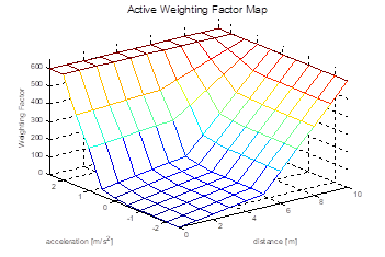
First, the weighting factor can be set by a sign of acceleration to against collision. While preceding vehicle is decelerating with small gap, subject vehicle has to decelerate fast to avoid crush. Another influence is a relative distance. When preceding vehicle accelerates with small relative distance, the subject vehicle should not follow too fast because the target vehicle has possibility to decelerate soon. On the other hand, the subject vehicle has more weighting factor not to miss the target with big relative distance.
The active weighting factor map has two input, acceleration and relative distance, and output as weighting factor as Fig. 2. Fundamentally, the factor is high. If it is high enough, controller can against big acceleration. Therefore, the fuel efficiency is expected higher and following performance for preceding vehicle is lower. Using this map, however, the controller maintains safety with low weighting factor while minus acceleration of target vehicle and small distance between subject and target.
3. Simulation and Result
The optimal control with active weighting factor algorithm is simulated using Simulink® for control algorithm and CarSim® for vehicle model. The Simulink® is a simulation tool for model-based design and CarSim® is a co-simulator with vehicle dynamics. The simulation environment has set with real vehicle model and legislative driving cycle. This simulation is focused on fuel efficiency and following performance as safety side both.
3.1. Simulation Environment
A conventional SUV (Sport Utility Vehicle) using 2.2 diesel engine is modelled for controlled vehicle and FTP-75 (EPA Federal Test Procedure), commonly known as city driving cycle, is used to verify effectiveness of the algorithm. This driving cycle is not only legislative, but also frequent acceleration and deceleration are suitable for the system.
Compared controllers are simple PI controller (Proportion-Integration controller), basic LQR method with fixed weighting factor and LQR with active weighting factor. The simple PI controller is used control parameters from a preceding study by Rajamani [8]. LQR controllers with fixed factor are each designed by two different weighting factor. One of the controllers is used weighting factor for following performance and the other factor is selected for fuel efficiency because the two control goals are trade-off. Active LQR controller is adapted the map of active weighting factor as figure 2.
3.2. Simulation Result
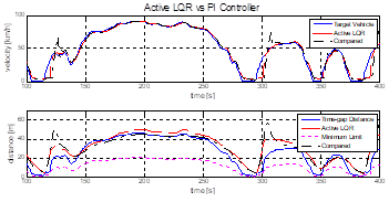
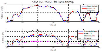
The summary of the simulation result is showed as Table 1 and Figure 4, 5, 6. The table contains each amount of fuel used and the figures represent time-gap distance errors.
Fuel efficiency of simple PI controller is lowest as 9.95 km/L because it controls subject vehicle only to consider time-gap distance. Even the PI controller has only goal, it makes more overshoot. Thus, fuel efficiency is lower and following performance is not better than others.
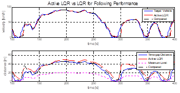
Two compared LQR controllers have different
character by a parameter setting. They bring about different results; the
algorithms are same though. When the weighting factor ![]() is a low value and focused on following performance as LQR#1 in Table 1 and compared in figure 5, relative distance trajectory is almost same as time-gap
distance. For this setting, however, affects low fuel efficiency. If
is a low value and focused on following performance as LQR#1 in Table 1 and compared in figure 5, relative distance trajectory is almost same as time-gap
distance. For this setting, however, affects low fuel efficiency. If ![]() factor is set a high value, the controller
has higher fuel efficiency than the previous setting, but it has big distance
errors.
factor is set a high value, the controller
has higher fuel efficiency than the previous setting, but it has big distance
errors.
Finally, the Active LQR controller has higher fuel efficiency than other controllers. At the same time, distance errors are much lower than LQR for fuel efficiency and similar to the others.
Table 1. Summary of the Simulation Result.
| Simple PI | Basic LQR#1 | Basic LQR#2 | Active LQR | |
| Fuel Consumption (kg) | 1.017 | 0.787 | 0.775 | 0.757 |
| Fuel Efficiency (km/L) | 9.95 | 12.86 | 13.07 | 13.38 |
Fuel efficiency of Active LQR is improved 34.5%, 4.0%, and 2.4% from others.
• Simple PI: PI controller for normal
with parameters set: Kp=1, Ki=0.3
• Basic LQR#1: LQR for following performance
with parameters set: ρ1=1, ρ2=50, r=1
• Basic LQR#2: LQR for Fuel Efficiency
with parameters set: ρ1=1,
ρ2=50, r=500
• Active LQR: LQR for Optimal basic LQR#1 and #2
with parameters set: ρ1= 1,
ρ2= 50, r=Map as figure 2.
4. Conclusion
This study suggests the control algorithm for improving fuel efficiency on adaptive cruise control system. The algorithm is extended using variable weighting factor from preceding study which is linear quadratic regulation. Therefore, it controls the subject vehicle to improve fuel efficiency and to keep time-gap distance from preceding vehicle at the same time. This algorithm is operating the vehicle similar to human driver being.
However, this paper arrived at the result by a limited simulation of deduction, also the driving cycle is not for adaptive cruise system. The future study will develop and verify with more exclusive driving cycle for the system. Furthermore, the real-world test is demanded for the more accuracy.
Acknowledgements
This work was supported by the Industry Core Technology Development Project (grant no. : 10052501) from the Ministry of Trade, Industry and Energy, Republic of Korea. And specific project name is development of design technology of a device visualizing the virtual driving environment and synchronizing with the vehicle actual driving conditions to test and evaluate ADAS.
References
[1] C. Marino, A. Nucara, M. Pietrafesa, and A. Pudano, "The Assessment of Road Traffic Air Pollution by Means of an Average Emission Parameter," Environmental Modeling & Assessment, vol. 21, no. 1, pp. 53-69, 2016. View Article
[2] F. Nejadkoorki, K. Nicholson, I. Lake, and T. Davies, "An approach for modelling CO2 emissions from road traffic in urban areas," Sci Total Environ, vol. 406, no. 1-2, pp. 269-278, 2008.View Article
[3] Y. Zhang, Choyu Lee, Hua Zhao, Tom Ma, Jing Feng, Zhiqiang Lin, Jie Shen, "Improvement of Fuel Economy and Vehicle Performance Through Pneumatic Regenerative Engine Braking Device (Reneged)," in Proceedings of the FISITA 2012 World Automotive Congress, 2013, pp. 55-66, Springer. View Article
[4] C. Brace, M. Deacon, N. Vaughan, R. Horrocks, and C. Burrows, "The compromise in reducing exhaust emissions and fuel consumption from a Diesel CVT powertrain over typical usage cycles," in Proceedings of CVT’99 Congress, Eindhoven, The Netherlands, 1999, pp. 27-33.
[5] J. Ino, T. Ishizu, H. Sudou, and A. Hino, "Adaptive cruise control system using CVT gear ratio control," SAE Technical Paper 0148-7191, 2001. View Article
[6] H. Peng, Zheng Li, Bin Chen, Jieyu Wu, Zhenglan Zhao, Yuehong Shu, Junjun Lei, "Development for Control Strategy of ISG Hybrid Electric Vehicle Based on Model," in Proceedings of the FISITA 2012 World Automotive Congress, 2013, pp. 333-342, Springer. View Article
[7] O. Erdinc, B. Vural, and M. Uzunoglu, "A wavelet-fuzzy logic based energy management strategy for a fuel cell/battery/ultra-capacitor hybrid vehicular power system," Journal of Power sources, vol. 194, no. 1, pp. 369-380, 2009. View Article
[8] R. Rajamani, Vehicle dynamics and control. Springer Science & Business Media, 2011. View Book
[9] E. Kim and E. Choi, "Estimates of critical values of aggressive acceleration from a viewpoint of fuel consumption and emissions," in 2013 Transportation Research Board Annual Meeting, 2013. View Article
[10] K. Ahn, H. Rakha, A. Trani, and M. Van Aerde, "Estimating vehicle fuel consumption and emissions based on instantaneous speed and acceleration levels," Journal of Transportation Engineering, vol. 128, no. 2, pp. 182-190, 2002. View Article